
C3 basic

Why the C3 basic?
The ESP32-C3 is a great basis for small battery powered projects. Less power hungry than 'full fat' ESP32s but still capable of Wi-Fi or Bluetooth connections, just enough GPIO to get stuff done and loads of Flash and SRAM compared to ESP8266 based boards. Support in the Arduino IDE is now good and almost all ESP32 based projects work on the C3. Beware that the C3 has no touch pin support. Check the Espressif site for the full list of C3 features.
Many of the C3 based boards have little 'value adds' like an addressable pixel or use a separate USB to UART convertor. These things suck power and use GPIO. This is about as close to a bare C3 module as you can get. The only 'value add' is a resistor ladder on GPIO-0 to act as a battery monitor.
Pinout & GPIO
To connect a USB breakout you just need the 5V, GND and USB D+/- pins connected. See the third image for an example of how to connect a common micro-USB breakout. The board pinout is deliberately made so one of these micro-USB breakouts can be connected easily by soldering it to the board with a header if you wish.

A lot of the time though you may want to use all the GPIO so we ship these with a basic OTA firmware that will allow you to do over-the-air updates from the Arduino IDE.
When using the Arduino IDE to program this board select 'ESP32C3 Dev Module'. If you want to program it again over USB without having to push the 'Flash' button be sure to select "USB CDC on boot: Enabled".
Should you want to put the C3 in 'Flash mode', hold down the 'Flash' button while pressing 'Reset' or when you apply power to the board.

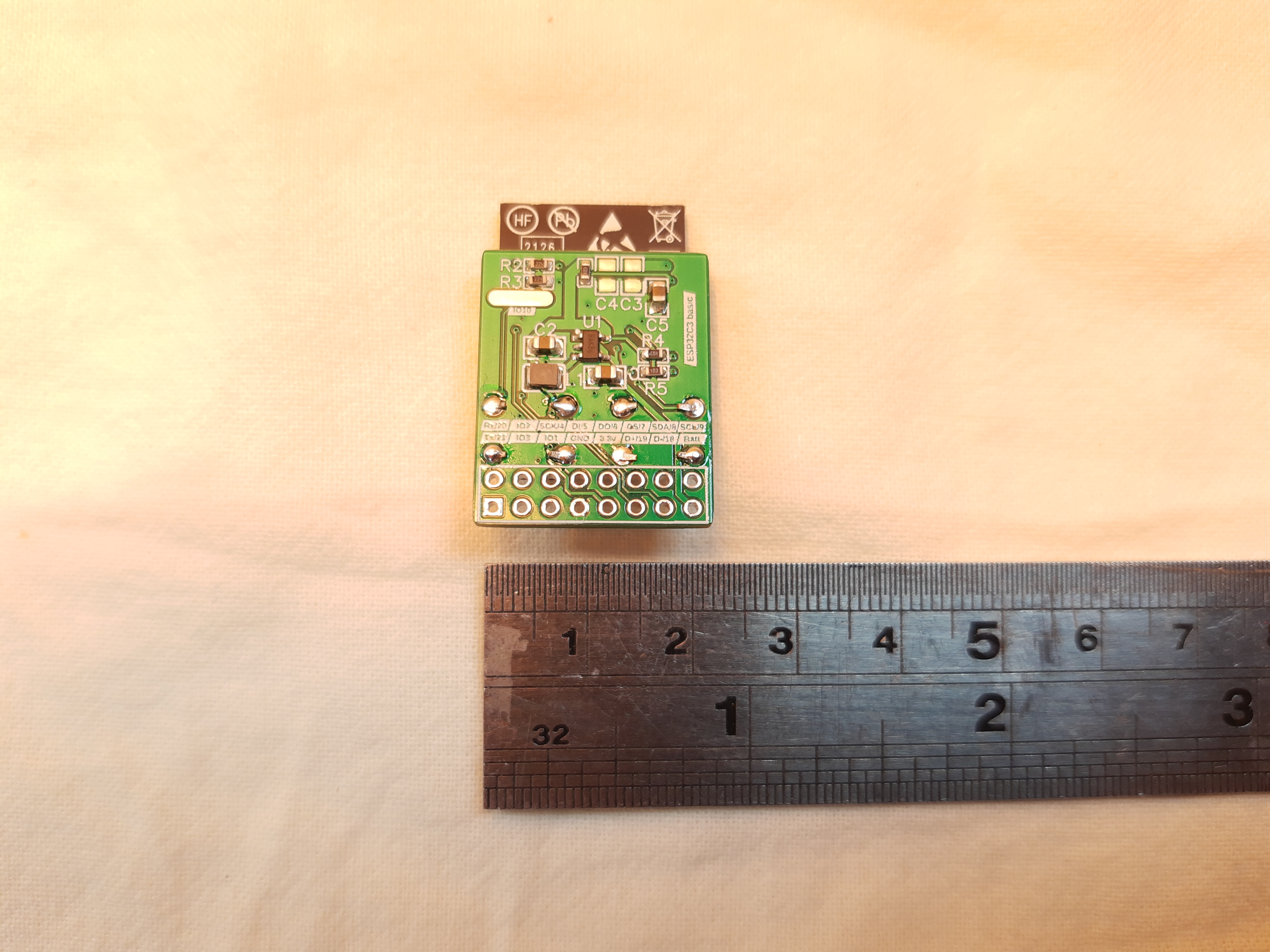
| 0 | 1 | 2 | 3 | 4 | 5 | 6 | 7 |
|---|---|---|---|---|---|---|---|
| RX/GPIO-20 | GPIO-2 | SCK/GPIO-4 | MISO/GPIO-4 | MOSI/GPIO-6 | CS/GPIO-7 | SDA/GPIO-8 | SCL/GPIO-9 |
| TX/GPIO-21 | GPIO-3 | GPIO-1 | GND | 3.3v | USB-D+/GPIO-19 | USB-D-/GPIO-18 | Battery/Vcc |