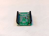
ESP32-CAM Backpack
A simple 'backpack' for the popular ESP32-CAM development board with a more efficient voltage regulator, battery monitoring resistance ladder, power and GPIO broken out.This product does not include an ESP32-CAM development board.
The ESP32-CAM Backpack is available on Tindie.
Why use an ESP32-CAM Backpack?
If you've ever used and ESP32-CAM, especially when powering it from a LiPo cell, you will have probably experienced brownouts and generally flaky behaviour.This is often because the 3.3V LDO fitted is an AMS1117 or similar which come with a rather large 1V minimum voltage drop under real load. This is fine, if wasteful, if your power supply is a solid 5v from the mains supply. All LDOs just turn the excess voltage into heat, but start using batteries and this sucks.
Try to drive an ESP32-CAM from a LiPo cell and shortly after you've connected it the ESP32-CAM will be getting ~3.0v rather than 3.3v and the bulky of the battery capacity is pretty much unusable.
The ESP32-CAM Backpack bypasses the onboard LDO and delivers power with a buck regulator instead. The theoretical efficiency gains of using a buck convertor going from 3.6-4.2V down to the 3.3V needed for the ESP32 aren't anything to write home about but you do get to use much more of the capacity of the cell. Which is a big bonus.
Power supply
The onboard buck regulator can nominally handle a supply of 3.3-5.5V but this was mostly designed for use with a single LiPo cell at 3.6-4.2V. In total the regulator can supply up to 800mA which should be enough for any reasonable battery powered device involving an ESP32-CAM.If you want to use 4x Alkaline cells then while it's nominally out of spec I have found the buck regulator I've used actually works fine at ~6V and above about 6.5V shuts down, working again once the supply drops back below 6V.
Note it will not work at the 7.2V+ that a 2S LiPo setup provides.
The output from the 3.3V regulator is broken out on the back of the backpack giving three connections for other peripherals should you want them.
Supplying power is done from the two solder points on the 'bottom' of the board. There is also a large round pad in the middle of the board that we intended to make use of as the contact for an 18650 battery. We did not use this in the end but there is nothing stopping you from doing so.
The buck regulator has a low voltage lockout at 2.5v that will protect your cells from over-discharge over a short period. However with the resistor ladder and 40μA quiescent current of the regulator in shutdown, you should not leave cells powering the board over a long period as they will eventually over-discharge.
Onboard battery monitoring
To give you a very basic measure of battery life we've included a simple resistance ladder connected between the power and ground to GPIO12. The resistors are 330k/100k so can handle a decent voltage range if you're not using LiPo cells.
For estimating life I've taken to using the polynomial curve approximation from G6EJD.
GPIO breakout
Another minor gripe with the ESP32-CAM is that they typically come fitted with pin headers, which isn't great for soldering to. The ESP32-CAM Breakout comes fitted with matching header sockets so it just plugs in. There are then unpopulated headers on the rear of the ESP32-CAM breakout for attaching peripherals by GPIO though as you'll appreciate, there are limited usable GPIO on an ESP32-CAM especially if you use the SD card.
Mounting holes
There are four mounting holes on the ESP32-CAM Breakout.
- Left to right the spacing is 17.8mm.
- Top to bottom the spacing is 23.4mm.
What the ESP32-CAM backpack is not!
This will not transform your ESP32-CAM into an efficiently designed low power camera board. For that you probably need to start from something else. What it does is give you a low effort way to battery power and ESP32-CAM that gets your project underway.
I designed these just for that purpose in my own projects and they worked out well so I thought I'd put up some for sale.
How to connect the ESP32-CAM Backpack
It should be orientated so that if the ESP32-CAM antenna is facing downwards then the writing on the ESP32-CAM Backpack is the right way up. See the first photo for reference.


